Warning You're reading an old version (v5.2) of this documentation.
If you want up-to-date information, please have a look at master.
Data Geometry
MARE2DEM uses a right-handed coordinate system with the z axis positive down. x is the model strike direction where conductivity is invariant.
Note
There is no assumption about where \(z=0\) resides in the model or data spaces, although generally it is recommended to set \(z=0\) to be sea level. Similarly, transmitters and receivers can be located at any x position, but generally they should be close to \(x=0\).
Receiver Geometry
The figures below show the receiver position geometry.
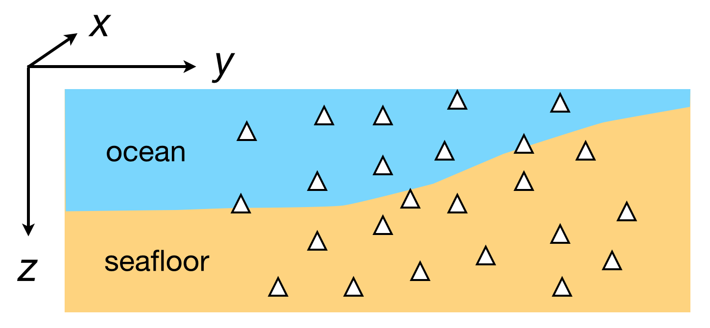
Fig. 27 Receivers can be located anywhere in the model (air, ground surface, sea, seafloor, subsurface)
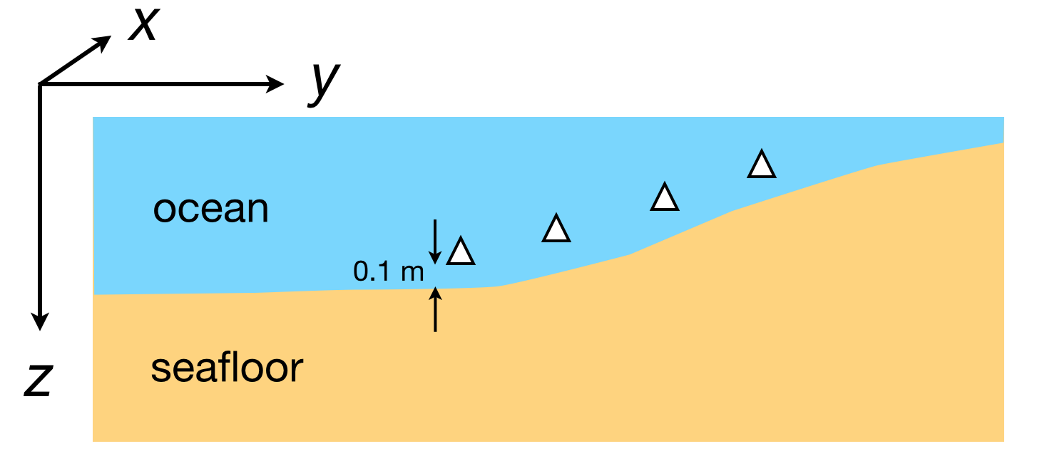
Fig. 28 Seafloor EM and MT stations should be positioned slightly above the seafloor to avoid a numerical ambiguity when the station is precisely on the boundary between sea and seafloor. A vertical offset of about 0.1 m works well. Seafloor topography (with z defined positive down) can be interpolated to the receiver position and then the receiver depth can be set to \(z_{rx} = z_{seafloor}-0.1\).
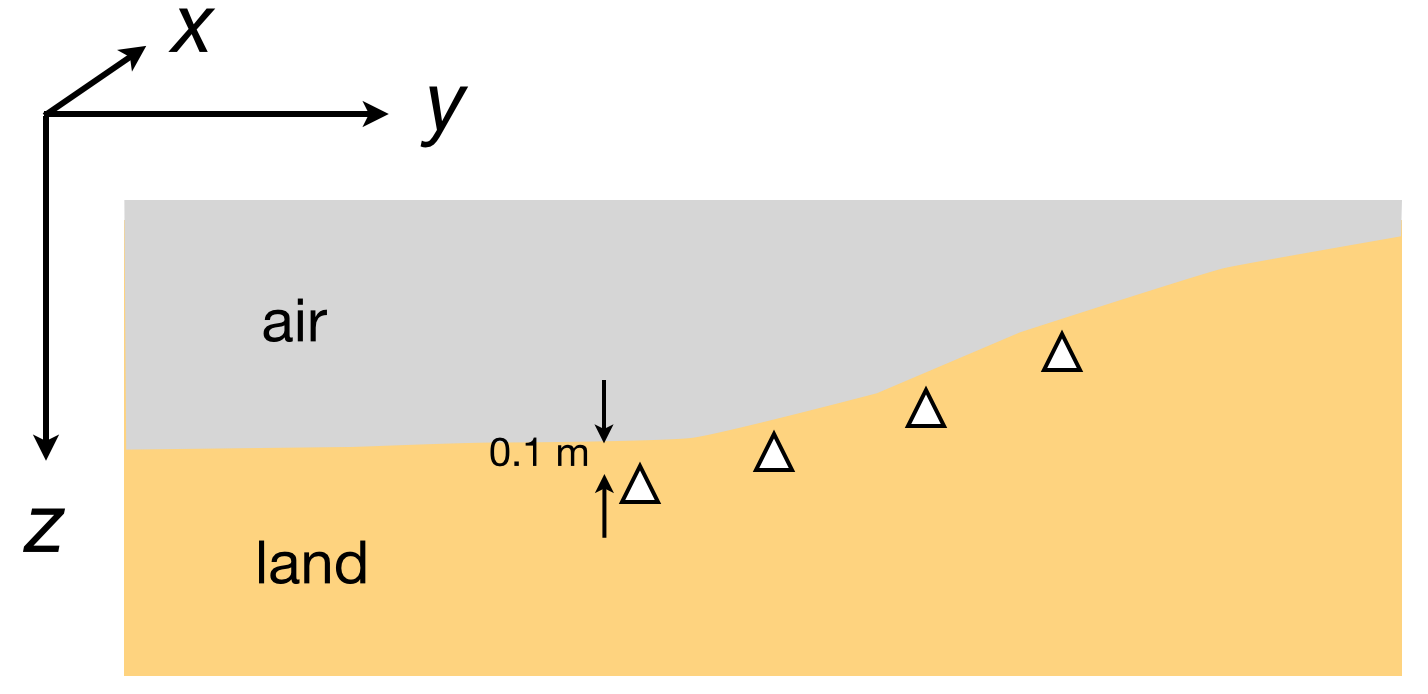
Fig. 29 Land surface EM and MT stations should be positioned slightly below the seafloor to avoid a numerical ambiguity when the station is precisely on the boundary between sea and seafloor. A vertical offset of about 0.1 m works well. Land topography (with z defined positive down) can be interpolated to the receiver position and then the receiver depth can be set to \(z_{rx} = z_{land}+0.1\).
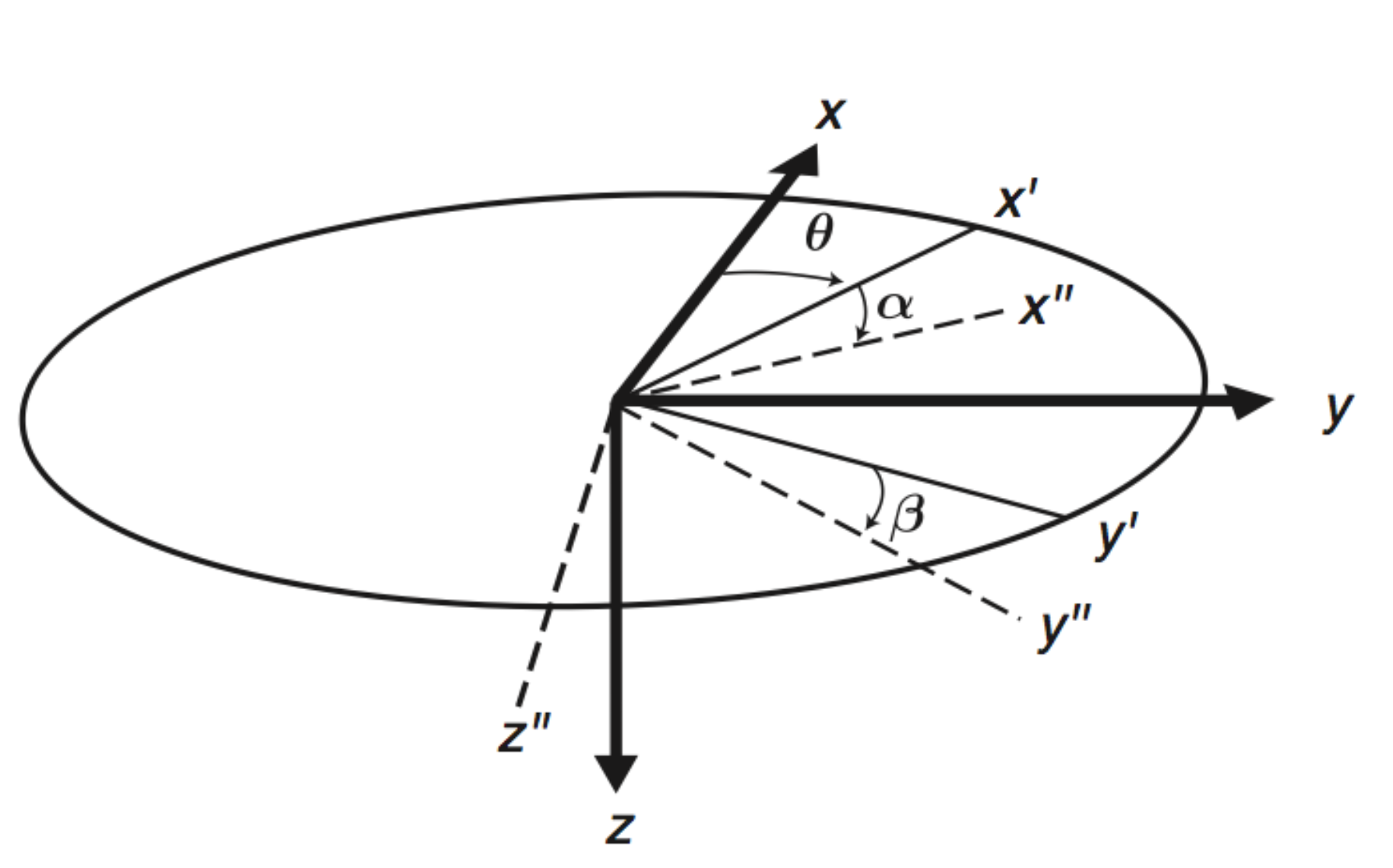
Fig. 30 A full 3D rotation of the modeled receiver is possible using the three angle defined in this image. However, we recommend rotating the data to the x,y reference frame so \(\theta = 0\) and \(\alpha = 0\) and then possibly specifying a non-zero 2D tilt angle \(\beta\) so that the y receiver component is parallel to the modeled 2D topography.
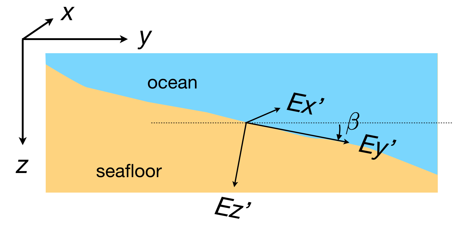
Fig. 31 The tilted receiver y’ component is specified by the \(\beta\) angle, defined positive down from the horizontal plane. For normal seafloor EM stations, this angle can be computed by the slope of the modeled seafloor topography. This example shows a positive \(\beta\) angle, which occurs when the topography slope is down to the right.
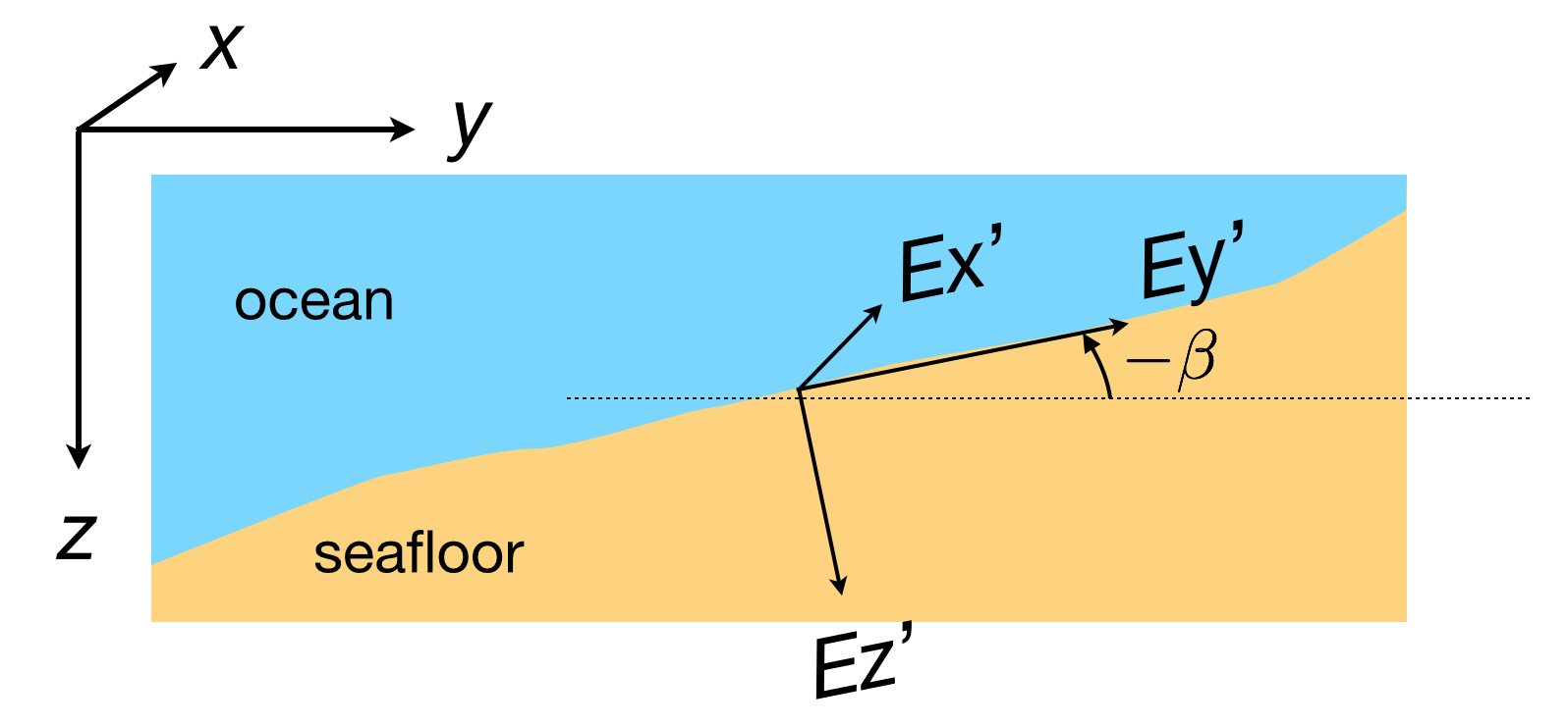
Fig. 32 This example shows a negative \(\beta\) angle, which occurs when the topography slope is up to the right.
Transmitter Geometry
MARE2DEM can model both electric and magnetic dipole sources. Magnetic dipoles are always assumed to be point dipoles while electric dipoles can be point sources or line sources via the length setting in the data file. The figures below show how the transmitter orientation angles are defined.
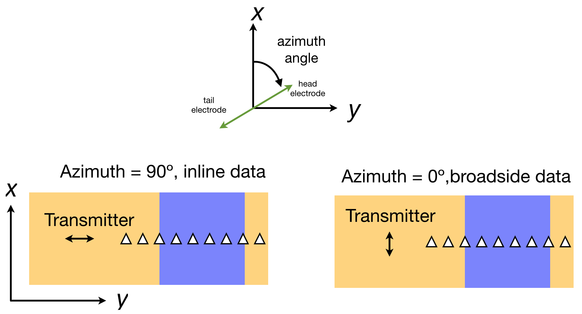
Fig. 33 The transmitter azimuth is defined as the horizontal rotation of the source axis, defined positive clockwise from x. For normal inline 2D CSEM surveys, receivers are positioned along the y axis and the transmitter has an azimuth of 90º (or 270º). Conversely, a broadside source has an azimuth of 0º (or 180º).
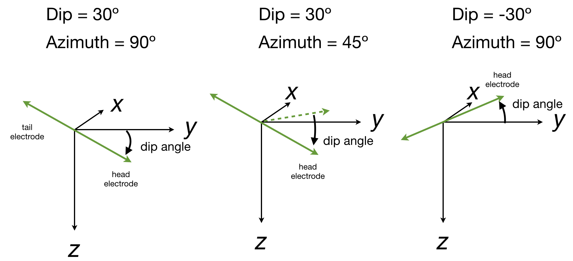
Fig. 34 The transmitter dip angle is defined as positive down from the horizontal plane.
Receiver and Transmitter Gathers
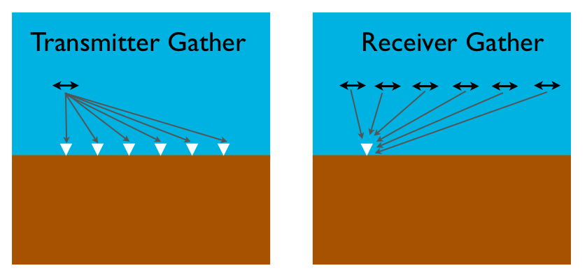
Fig. 35 This is just for terminology used in the CSEM response plotting code. CSEM data can be plotted as gathers with respect to the transmitters or the receivers, much like seismic shot and receiver gathers. A transmitter gather plots a line for the data at all receivers for a single transmitter position. A receiver gather plots a line for the data on a single receiver for all transmitter positions.
UTM Reference
Note
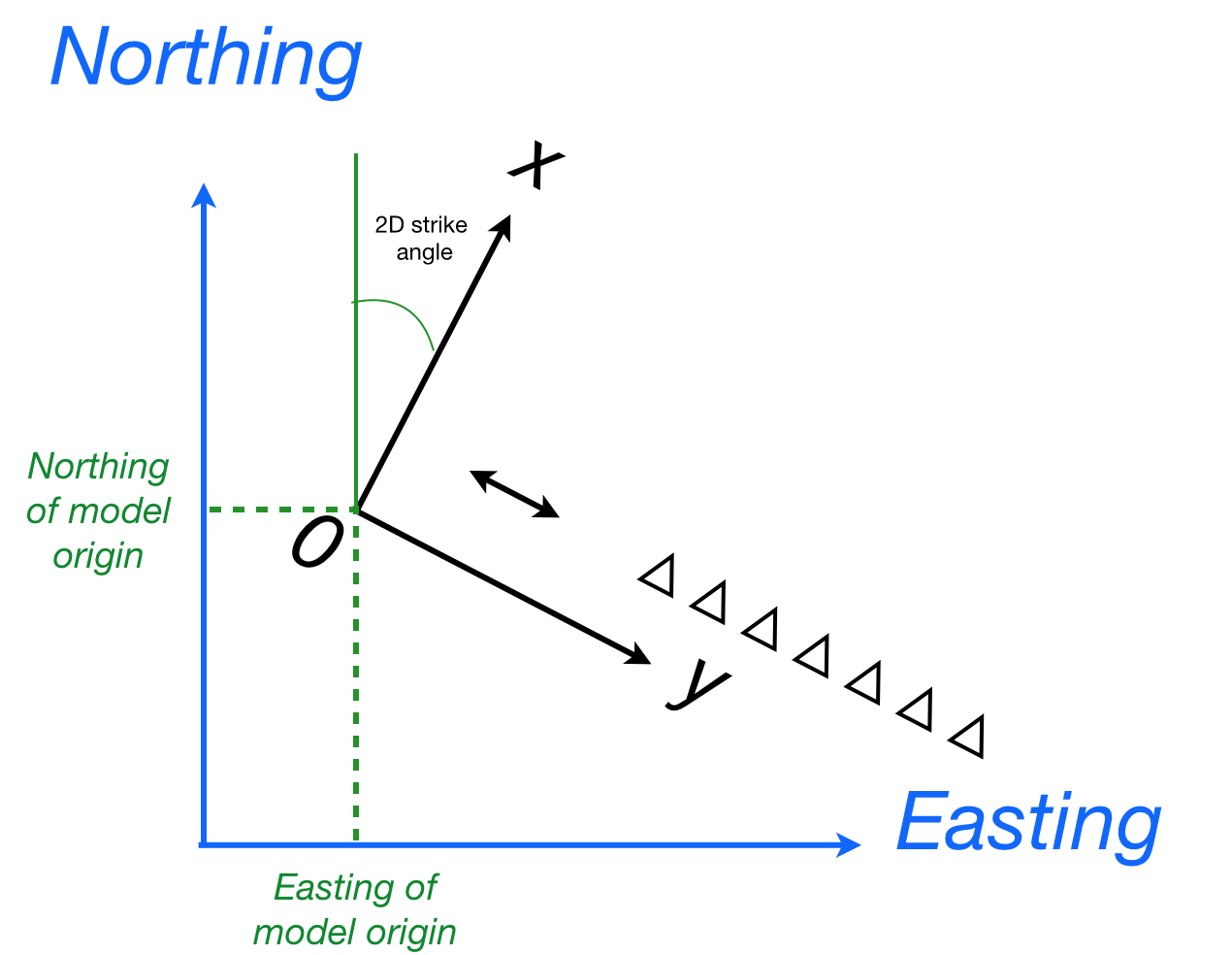
UTM referencing is only used for plotting purposes. MARE2DEM completely ignores this for the 2D EM calculations.
To help with post-inversion plotting of well logs and SEG-Y seismic overlays on your 2D inversion models, the data file has a line for specifying the UTM zone, origin and rotation of the 2D model coordinates. The 2D strike angle is the geographic angle corresponding to the x direction of the 2D model, clockwise from north. The example below has a 2D strike of 20º. For more info, see Coordinate Transforms for Getting Data Into MARE2DEM.