Here we just state some quick tips about when to use reciprocity to
speed up CSEM computations; see the Electromagnetic Reciprocity section for
the theoretical background and more details.
The run time for MARE2DEM depends strongly on the number of CSEM
transmitters being modeled and less so on the number of receivers. Thus,
when the number of transmitters greatly exceeds the number of receivers
(more specifically, the number of receivers times the numbers of
receiver components being modeled) then electromagnetic reciprocity
should be applied to the input data file so that MARE2DEM can solve the
reciprocal problem more quickly.
When the number of transmitters greatly exceeds the number of receivers times the number
of components (per receiver). Reciprocity is almost always recommended for nodal seafloor
marine CSEM data since there are usually far fewer receivers than there are transmitter
shot points.
For land CSEM data, usually there are far fewer transmitters
than receivers and so reciprocity should not be applied.
For towed streamer CSEM data, the source moves with the attached towed receivers and so
reciprocity should not be applied since it offers no speed up advantage.
The geometry (location and angles) of the source and receiver wires
must be maintained for EM reciprocity to hold; thus a dipping transmitter source
becomes an identically dipping receiver at the same location, and likewise a real
tilted receiver will become an identically tilted (and located) transmitter.
An easy way to think about this is to consider the actual transmitter wire and the
actual receiver wire. Leave them as is (same location, same rotation and tilt angles),
and just reverse energize them, so that the source wire becomes a receiver wire and
the actual receiver wire becomes energized as the source wire.
The easiest case is for electric sources and receivers as shown in the
image below. If the receiver was instead a magnetic receiver component
(say the crossline magnetic field component), then the actual receiver
becomes a magnetic source (in the same direction and location as the actual receiver component)
and the actual sources become electric receivers.
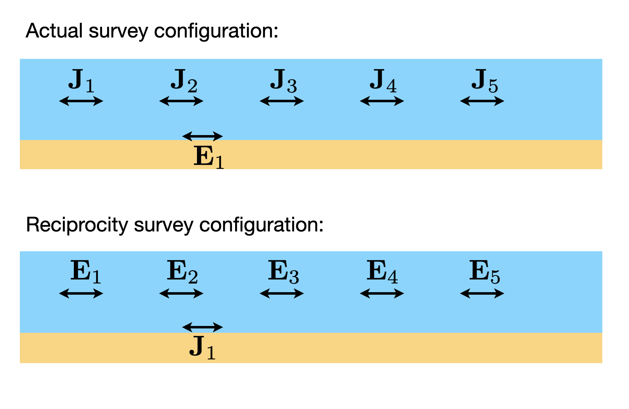
Fig. 40 Applying reciprocity to reduce the number of numerical transmitters
and thus speed up MARE2DEM. The top image shows the actual survey
geometry, where a single seafloor receiver recorded data points for
each of five different transmitter locations. This requires solving
five linear systems in MARE2DEM. The bottom image shows the
equivalent responses that can be generated through EM reciprocity,
where the five sources are turned into five receivers and the
original receiver is turned into a single transmitter, thus
requiring only a single linear system to be solved.